
Pneumatic components are the physical parts that make up a pneumatic system. They use compressed air or gas to generate, control, and convert power into mechanical motion. Main parts include air compressors, FRL preparation units, control valves, actuators, and connecting hoses.
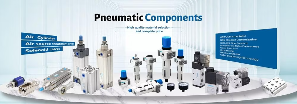




Our knowledgeable cost management experts to solve customers problems in one stop automations service. We provide wide range of combination brands to match the exact usage of the correct and competant components to maintain the automations process in full and max operation with min downtimes.
Pneumatic force calculations
Pneumatic system designs
Pneumatic troubleshootings
Pnematic cylinders custom fabrication
One stop supply in pneumetics control whole systems
Recommendation and advisory in replacements and installations.
Tests covering basic gas laws, circuit symbols, valve port numbering (e.g., port 1 for supply, 3/5 for exhaust), and cylinder operations.
The basic info requested is loads. Later it would be calculated according to cylinder bore and pressure supplied with the extending or retract lengths
Valve is been chosen according to control methods and air cylinder acting.
All acessories need to install according to fittings thread's size and tubing sizes in the whole system.
The force been calculated by checking the pressure meter in MPa, bar, kg/fcm2 or psi, then check the cylinder bore size and put in the below formula :
Ft = P × Au
where:
We successfully cope with tasks of varying complexity, provide long-term guarantees and regularly master new technologies.
(+380) 50 318 47 07
65 Allerton Street 901 N Pitt Str, Suite 170, VA 22314, USA